Foamboard is the answer
Wednesday, April 29, 2015
Random build of the day: a magnifying lens for Smartphone
Foamboard is the answer
Monday, April 20, 2015
DIY of the day: Adding heat spreader to Value RAM modules
Though heatspreaders are usually cool and good looking: If you have some old modules with ones, why not swapping them to the newly bought modules?
Disclaimer: your warranty is now void!
Repeat for the second clip.
The tricky part
On my Corsair modules the labels could be easily removed without tearing: i reused them later.
Once the clips are gone, the heat spreader will unfold open. It's time to swap the RAM modules:
/!\ Be extremely careful on the side facing you ==> the labelled side is ALWAYS looking toward the CPU on ATX Motherboards
- Once roughly adjusted, fold back.
- Make sure to adjust the Heatspreader position without tearing or wearing the heat-pad (grey part on the picture), do not press it to tight either.
- place the clips back in place: you should hear a "click" and the clips should be in the state they were before unfolding.
You now have your brand new value modules skinned as higher class ones, they won't reach a much lower CAS Latency, but might be able to support some more overclocking.
And... they simply look cool if not cooler than before
Saturday, April 18, 2015
Lower CAS latency on a legacy Computer: Is it worth it?
An old question was how CAS latency is important and impacts performace on a legacy computer (with a CPU that doesn't feature any L3 cache)
Modules used:
| Name | PC2- | Frequency (MHz) | CAS latency | Size (MB) per module |
| Nanya NT2GT64U8HD0BY-AD | 6400 | 800 | 6-6-6-18 | 2048 |
| Corsair Value Select VS2GB800D2 | 6400 | 800 | 5-5-5-18 | 2048 |
| Gskill Extrem2 PC6400PK | 6400 | 800 | 4-4-4-12 | 1024 |
| Gskill Extrem2 PC6400HZ | 6400 | 800 | 4-4-4-12 | 512 |
| Hynix HYMP564U64BP8-C4 AB-T | 4200 | 533 | 4-4-4-12 | 512 |
| Micron MT8HTF6464AY-53EB3 | 4200 | 533 | 4-4-4-12 | 512 |
Hardware & Software
MotherBoard: Gigabyte GA-M61PME-S2P
RAM : Tested Criteria
GPU : Geforce 8400GS
HDD : Seagate Barracuda 7200.8 250 GB (7200rpm)
CD/DVD : writer
Floppy
Single and Dual Channel CAS battle (DDR800)
Signle Channel (1*2GB) and Dual-Channel (2*2GB) results are the following:
- SC-5-5-5-18: 2369MB/s
- SC-6-6-6-18: 2252MB/s
- DC-5-5-5-18: 2861MB/s
- DC-6-6-6-18: 2643MB/s
| Upgrading from ↓ to → | Single Channel 5-5-5-18 | Dual Channel 5-5-5-18 |
| Single Channel 6-6-6-18 | +5 % | |
| Dual Channel 6-6-6-18 | +8 % |
There is definitely a performance increase in pure RAM bandwidth, though this has barely any impact on real life work on a legacy PC.
NB: i also tried to mix the Corsair (5-5-5-18) and Nanya (6-6-6-18) modules, the motherboard set them to dual channel even though the chips are quite differents... and gave the following result:
It down-clocked the RAM to 667MHz (351MHz), and reduced latency to 5-5-5-15; for a 2410MB/s bandwidth.
Sunday, April 12, 2015
DIY 4 pins CPU-Fan adapter to 4 pins CPU-Fan + 3 pins Case-Fan
Some Story background
After i saved the old Acer X1700 motherboard from trash by replacing capacitors, i noticed that the passively cooled GPU was overheating... 45-80+°C (idle/full)
It was time to add a case FAN ... - where ? ... There's no place in there!- Doesn't matter, there's place outside the case!
The real issue was the single FAN port on the motherboard, and no SATA/MOLEX port left.
Making the 4 pins to 4+2 pins
Why not 4 to 4+3?
Here is the scheme:
- The female 4 pins part is plugged on the motherboard CPU-Fan port.
- The Ground (black wire, pin 1), the +12V, the Sense (tachymeter) and the Control (PWM pulses) are wired to the CPU-Fan (4 wires PWM-capable), and
- the secondary (SYS) Fan only gets Ground and +12V.
- We have no use monitoring the rpm of that fan, and it may interfere with CPU-Fan control (on my testing AMD motherboard the CPU-Fan didn't work until i removed the sense connection on the secondary Fan.
| CPU-FAN | SYS-Fan |
|---|---|
|
|
Making of
What are those colors???
On the first test i had wired the GND to an orange wire, for the final build the color scheme is slightly different:
| MotherBoard | Main Cable part | CPU-FAN wires | Secondary wires | SYS-Fan |
|---|---|---|---|---|
|
|
|
|
|
Looks messy? and it is, but everything was done with what i had under the hand...
Results
IRL

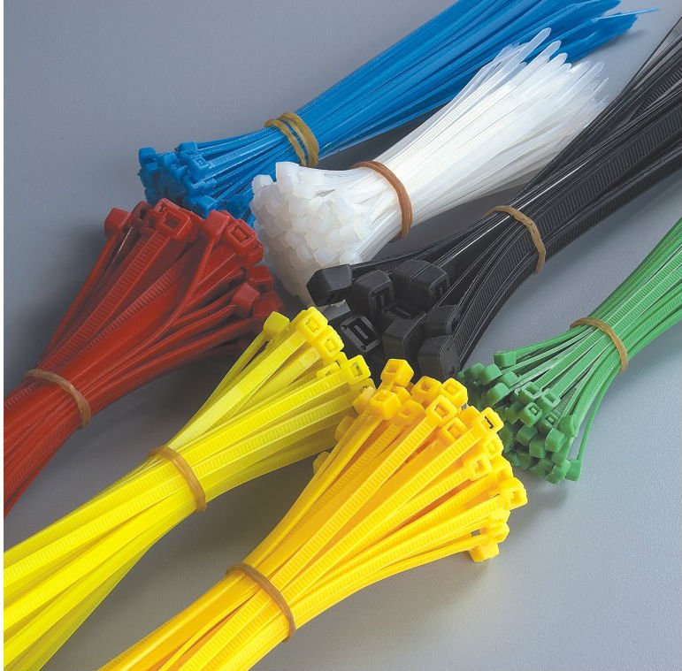
The Fan used is fixed with plastic ribbons
GPU Temperatures are really lowered:
| Before | After | ||
|---|---|---|---|
| Idle | Full | Idle | Full |
| 45°C | 80+°C | 37°C | 42+°C |


