Some Story background
After i saved the old Acer X1700 motherboard from trash by replacing capacitors, i noticed that the passively cooled GPU was overheating... 45-80+°C (idle/full)
It was time to add a case FAN ... - where ? ... There's no place in there!- Doesn't matter, there's place outside the case!
The real issue was the single FAN port on the motherboard, and no SATA/MOLEX port left.
Making the 4 pins to 4+2 pins
Why not 4 to 4+3?
Here is the scheme:
- The female 4 pins part is plugged on the motherboard CPU-Fan port.
- The Ground (black wire, pin 1), the +12V, the Sense (tachymeter) and the Control (PWM pulses) are wired to the CPU-Fan (4 wires PWM-capable), and
- the secondary (SYS) Fan only gets Ground and +12V.
- We have no use monitoring the rpm of that fan, and it may interfere with CPU-Fan control (on my testing AMD motherboard the CPU-Fan didn't work until i removed the sense connection on the secondary Fan.
| CPU-FAN | SYS-Fan |
|---|---|
|
|
Making of
What are those colors???
On the first test i had wired the GND to an orange wire, for the final build the color scheme is slightly different:
| MotherBoard | Main Cable part | CPU-FAN wires | Secondary wires | SYS-Fan |
|---|---|---|---|---|
|
|
|
|
|
Looks messy? and it is, but everything was done with what i had under the hand...
Results
IRL

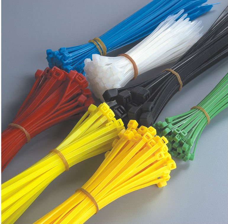
The Fan used is fixed with plastic ribbons
GPU Temperatures are really lowered:
| Before | After | ||
|---|---|---|---|
| Idle | Full | Idle | Full |
| 45°C | 80+°C | 37°C | 42+°C |


No comments:
Post a Comment