Thursday, September 14, 2017

Radio Frequency Interference : USB3.0 and 2.4GHz wireless devices

There's quite a long time I didn't post anything out there. It's time to start again with a very quick and dirty post!
I recently bought a USB3.0 Hub and plugged my Logitech Unifying receiver in it, everything was going well, until I plugged a USB3.0 SSD in it too.

Let's find why!


The HUB
US3.0 type C to 3xUSB3.0 type 1 + 10/100MB/s ethernet

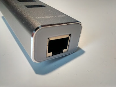
The considered USB HUB is the following : a US3.0 type C to 3xUSB3.0 type 1 + 10/100MB/s ethernet Hub, sold by Lention.
NB: As you can see the USB cable is pinched by the aluminium casing, but this shouldn't affect performances.


The Issue
USB3 doesn't like 2.4GHz

If my Logitech Unifying dongle is plugged in the Hub, and files are transferred from an external USB3 drive, then the mouse is behaving erratically.


if it is plugged directly in a spare USB3 port on the laptop and that the Hub is at a fair distance, everything is ok.

Using a wireless device near a USB3 hub isn't a great idea, Intel explained why and how to mitigate that issue in 2012.


Radio Frequency Interference
a noise story

This Intel white paper explains why better than I ever will.
In short, the USB3.0 device emits radio frequencies in the 2.4GHz range and interfere with wireless device by increasing noise level, which at a certain point can mess up with throughput and even break the link.
  • either the brand that makes the USB3 device shields it properly,
  • or the user needs not to put a wireless antenna (WiFi, Bluetooth or any 2.4GHz wireless) near the USB3 device...
  • or, the user can wrap the device with metallic tape as Intel demonstrated in the white paper

Saturday, November 12, 2016

HDMI to VGA Converter, an other Upcycling project

One does not simply trash things at home, every object that can be repaired should be.
Recycling is a thing, Upcycling is another.
  • Recycling is trashing unused or broken goods into pieces, revert them to raw material and use them to rebuild new things
    Usually you can't do it at home.
  • Upcycling is reusing things, either as is, or using parts of them to make others. That's something we can all do, the only things needed are time and will.
  • Upcycling in hight-tech is not only about being "Green" (and where is "Green" in playing with broken highly toxic high-tech materials?), not about saving money either (that converter is less than 10€ on ebay).
    It is more about being able not to throw away unused goods but give them another life.


HDMI to VGA + Audio converter
Why upcycling it?

I didn't have any of those HDMI to VGA converter, and they can come in handy sometimes. I found this one torn down, without its box, and some wires partially ripped off.
It was time to rebuild it.


The mod
Upcycling isn't only repairing but improving too

Beside repairing the converter, I got it modded with an external 5V 500mA input (USB).


Why adding that external 5V power supply, doesn't it gets its power from HDMI ?

HDMI 1.3 standard states the following limits: [source]

This converter is based on the LT8511A chip to convert HDMI digital signal to VGA+Audio analog signals (considering the datasheet, this chip is meant to be powered by an external source...)
This converter is used a lot by Raspberry Pi users that complain about burning a 200mA max rated diode with it and similar converter chips when powered directly by the HDMI input.
==> Looks like it draws a lot more than the 10~50mA expected, As my devices with HDMI output are quite old (the most recent is from 2013) I didn't want to risk the source in the eventuality it doesn't have any over-current protection.


Finding where to solder the +5Vin and mass wires

From the HDMI documentation we know that +5V is coming to the pin 18. Luckily the pins were numbered on the board, after checking continuity with a multimeter, pin numbered 18 was actually pin18 +5V as expected.


Testing

The USB cable used is from a R.A.T.5 mouse

The converter is detected as LTM 40" 1920*1080 display when plugged alone.
When an external display is plugged in, the converter passes through the display specs to the PC:


Finding a case

To stay in the same idea, I couldn't simply go an buy a case. So I took the first plastic case that was there: a battery case for a led strip light (that has already been re-purposed)
Here is the result:

Yeah, Hot glue everywhere...
PS: the audio works well too


Conclusion
Not pretty, but it works.

The result may not be pretty, but it definitely works well. And it proves again that something that was meant to be recycled could be still used after some repair and work on it.
This project has been 99% made out of trashed materials: even the screw is from an old electronic component, only hot glue and solder aren't.
PCBs are hard to recycle, so using a device longer and/or repairing it is "greener" than buying a new device -and paying a few € cents of "green tax" regardless the human work cost of it-.

Whenever possible:
  • Don't trash,
  • Don't recycle,
  • Upcycle!

Monday, August 22, 2016

Inateck USB3.0 to IDE + SATA converter: Read your old drives on recent devices!

A few friends of mine needed data recovery from old broken computers they had. Most of them had a tower form factor PC with old IDE drives or more recent ones with SATA port.
For those no issue: Having old working PCs around ... Only needed to drop the HDD in the PC and voilà.
But recently, two friends had Laptops IDE HDDs and i had no way to save their data!


Inateck USB3.0 to IDE + SATA converter
A kind of a Savior

To be able to read these old laptop IDE HDDs i needed something new. Here is what i needed: The ability to
  • access SATA drives (to use 3.5" HDD on a laptop)
  • access old 3.5" IDE drives
  • access old 2.5" IDE drives (what I specifically needed this time)
  • an external PSU, that's not the poor 5V 500mA that will power a 3.5" IDEdrive
  • a power switch button to be able to "hot swap" the converter and "cold swap" the drives


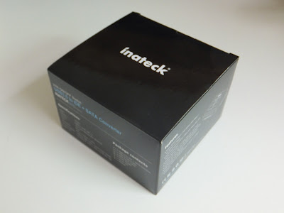
After some search I came across the Inateck USB3.0 to IDE + SATA converter [I am not affiliated in any way with Amazon or Inateck, this is just a personal experience.]


Unboxing
What's inside the box (for real?)

Advertised content is contractual with the description of the product:
There is:
  • The converter itself (model UA2001)
  • USB3.0 cable
  • Molex power cable
  • Power Supply (12V, 2A rated, with a 20AWGX2C; isn't 20AWG rated for 1.5A max?)
  • Driver CD, useless on linux
  • Instructions manual, explaining how to use the backup software
Converter sepcs:
  • SATA port
  • 44 pins laptop IDE port
  • 40 pins 3.5" IDE port
  • On the back side:
  • On/Off switch
  • 12V 2A input port
  • USB3.0 port
  • 12V+5V output port (for the MOLEX adapter)
  • On the top:
  • Backup button
  • power LED


Notes: The converter is made of quite thick and solid black plastic (1mm thick on the edges), it is not "pretty" but it looks tough and reliable (ok, the last thing that i thought was tough -a Nitecore flashlight- failed me).
The molex adapter is made of small gauge wires (20AWG) so it shouldn't be able to power a Sony Optiarc AD-5260S (5V/1.5A,12V/2.5A!)


Does it actually work?
Yes it does its job

Due to wide compatibility, either the drive or the converter is hanging and not lying on the table. This is not for daily usage in a crowded place but more as an occasional help.
It even works with more than one devices plugged: the datasheet says "Operates with one IDE and one SATA HDD Simultaneously"

Actually lsblk recognises correctly 3 disks when the 2 IDE ports are populated and the SATA too (all with HDDs contrary to the picture above). (though i didn't tried to read/write massive amount of data simultaneously)
sda: internal HDD
sdb: SATA HDD
sdc: 2.5" IDE HDD
sdd: 3.5" IDE HD


So it works on Linux computers, but can we use it as USB OTG reader for an Android device?


OTG mode
What about android?
Let's say you don't have a PC (as if it died, but the HDD and your data are still safe but unreachable).
This adapter works flawlessly in OTG mode using a simple OTG cable used to read USB flash-drives on Android devices.
There's nothing to fear about, the power supply of the HDD is done by the adapter PSU so the Android device won't drain itself trying to power it.


Conclusion
Global feelings

The overall quality of the product is quite good considering the price.
I think it is a great product for the usage i have i.e. data recovery once in a while. But it is definitely not for professional or intense usage like 7hrs/day&5days/week. (less compatible and more specific devices would do the job better, like one for SATA, one for 40pins IDE and one for 44pins IDE)
It has great compatibility both with devices and hosts: it could read anything i tried (SATA/IDE HDDs, IDE and SATA CD/DVD drives) on any platform (Windows, Linux and Android [sadly CD/DVDs couldn't be read on my smartphone])

Sunday, June 19, 2016

Repairing a Cyborg R.A.T.5 with an old Acer Mouse: Frankenstein Project

One does not simply trash things at home, every object that can be repaired should be. Here is the story of a broken Cyborg R.A.T.5: it came home broken, and was 'resuscitated' like a Frankenstein's monster. But is it fully back to life?


The R.A.T.5
Which disease killed it?

  • Main symptom: no left click
  • Secondary symptoms: Some of the secondary button facings are broken, ghost click sometimes happen

==> Looks like the left click button spring is bent or broken, this can be "easily" fixed if bent. Though if it is broken, it needs to be replaced (either the whole button casing, or only the spring if possible).

Disassembly
As a video is better than a written tuto, here is one made by Kuba Orpel:

To open the button casing: pry the little clips on both sides if possible (on the RAT5 left button only left click can be reached)

See how the clips look on this top button casing (black) from an Acer NetScroll mouse (the donor, as explained later)

A little button spring will pop: (see the break-line on the bent part, this one is dead and need to be changed)
Do NOT loose the little green piece (for the RAT5, red for the Acer here), use some tape to stick it in place: it will come handy in the process of re-assembly
The Donor
An old mechanical mouse: the Acer NetScroll


Donor spring in its original place:

The donor Button and the faulty one: they are not the same shape, but the same size... so one can take the other's place

The Repair
Swaping springs

Re-assembly is quite tricky:
  1. The contact part should be placed under the contact pin,
  2. The bent part should be placed towards the indentation of the center pin, and gently forced into it
  3. The triangle part should be pulled gently and its indent placed against the last pin
  4. Pushing the center of the spring should make a click sound : it's correctly placed
Be careful: the process is try 'n fail, and the spring is really easy to break!!!
The Acer button spring in place in the R.A.T.5 button bottom casing:

Re-assembling the top case isn't difficult -as long as the previous part was a success-.

Is it fixed?


Hmmm, yeah the left click is back to life... but it still has a kind of ghost click for which i din't catch the cause yet... maybe one of the side buttons is dead or something (i already scraped two of the side ones without success)
Half a success, but still something to consider,
So the Frankenstein project is still a WIP... I'll update as soon as I find the definitive fix for the ghost click.
Note that i have already saved my own Logitech M505 from death by re-bending the spring of its left button. that spring issue is well known and well documented, but it is always nice to know that it can be possible to swap spring of some switches without having two broken mice.

Monday, February 29, 2016

"Unbreak" Wacom Intuos CTL-480 on Linux Mint 17.3

With the 17.3 update of Linux Mint, the GUI that allow to set parameters for the Wacom CTL-480 broke (it doesn't recognize it anymore), but the CLI "xsetwacom" still works fine.
In my previous article i already had pointed that the GUI wasn't perfect, now it's worse ...
The only thing i need (for now) is to switch between Absolute and Relative modes for the stylus. So this will be the only thing i'll cover here (for now).
Let's workaround with a shell script that auto-switches between modes at each launch.


Xsetwacom commands
How to... by hand?

To display wacom devices attached there is the following piece of code:
xsetwacom --list devices

On my side, this outputs the following:
Wacom Intuos S Pen stylus        id: 14 type: STYLUS    
Wacom Intuos S Pen eraser        id: 15 type: ERASER    
Wacom Intuos S Pad pad           id: 16 type: PAD

To get the mode for the stylus:
xsetwacom get "Wacom Intuos S Pen stylus" mode

To set Relative mode for the stylus:
xsetwacom set "Wacom Intuos S Pen stylus" mode relative

The script
The power of sed
As the output of "xsetwacom --list devices" is longer than the string needed for the set command, let's trim it with sed: (the following command allows variation in the device name, as when the tablet is connected with the wireless module it has "(WL)" in its name.
Note that the gap after the used name is variable (it is made of zero or more space(s) and one indentation, the sed command takes care of that)


Then the script will check for the mode and switch between both!

To launch the script, refer to my old post about m505 remapping script.
The potential updates to this script will be available on my github.

Saturday, January 9, 2016

Quickie #6: Nitecore MT06 and Thermal Throttling

I recently bought a Nitecore MT06 at my local retailer (i went in to get a Nitecore Tube, but bought both the Tube, and the MT06. The Nitecore MT06 is a great pen sized flashlight featuring a 165lm max light output.. but for how long before the thermal throttling feature starts?


The specs
the official ones


Benchmarking
The tools

To get an idea of the flashlight performance i needed a way to measure the Luminous intensity (cd). Having no professional tool for that i used the CT406 light sensor that is embedded in the Moto G first gen (XT1032) : the results won't be complying with the ANSI/NEMA FL1 standard but will be good enough to get our own idea of the flashlight performance.

Tools and Methods:
  • Power source: 2*AAA Energizer Rechargeable NH12 (Brand New)
  • Light sensor: CT406, giving results in illuminance in Lux(lx) turned into Luminous intensity via this formula:
    Iv(cd) = Ev(lx) × (d(m))^2
  • Calculated light output in Lumens (lm) :
    lm = cd × ( 2π(1 - cos(apex angle in °/2)) )
  • Calculated throw (beam distance in meters) :
    throw (lm) = sqrt(candela/0.25)
How to get the experimental light outpout?
As written above, the formula is the following : lm = cd × ( 2π(1 - cos(apex angle in °/2)) )
The measured apex angle is roughly 18° (result that we also can get using the advertised light output and the peak beam intensity [165lm, 2120cd ==> 18°])


EDIT: How to get the Surface temperature?
A simple crappy medical contact less thermometer (the Powerscan TH23F -that i recently got for 3€, and does not worth much more-) allows to measure the surface temperature of the flashlight body (with a maximum inaccuracy of about 1°C) , this does not give the real chip temp, but gives some interesting clues.

The experiment was carried out during 40 minutes. In three phases :
  1. MT06 set to high, as long as it can (meaning until it was too hot to even touch and hold... the ON/OFF switch!
  2. After a two minutes cool down (from really hot to warm), another period on high mode. untill it reaches the same heat trigger : human pain...
  3. Sixteen minutes in low mode to see how consistent the light output is when regulated.


EDIT: A second experiment is now added : full run from max to 1lm, to show both thermal throttling and runtime


Results...

Measured vs Advertised specs (high mode):
The FL1 standard asks to wait for 30 to 120 seconds before measuring the peak beam intensity
The first result (max) is obtained right after turning ON the flashlight, the second (FL1) complies with the FL1 standard and is compared to the official specs.
AdvertisedMeasured
Peak Beam Intensity (max)2238 cd
Peak Beam Intensity (FL1)2120 cd2114-2135 cd
Light Output (max)173 lm
Light Output (FL1)165 lm163-164 lm
Beam Distance (max)94 m
Beam Distance (FL1)92 m92 m
Considering the inaccuracy of the angle measure and the use of a CT406 as light sensor, it seems that Nitecore claims are absolutely legit.

Measured vs Advertised specs (low mode):
AdvertisedMeasured
Peak Beam Intensity (FL1)422 cd
Light Output (FL1)32 lm32.5 lm
Beam Distance (FL1)41 m


... and Thermal Throttling

Here is what Nitecore says on the MT06 user manual : "NOTE: The MT06 will begin adjusting output lumens automatically after 5 minutes of use, thus preventing overheating and extending battery life"
Let's see how much this is true and how long we can get the advertised 165lm!

Having nothing to measure the own flashlight temperature, an apparent temperature has been used instead (human felt temperature in a subjective range : room temp, warm, hot, and too hot)


  • Phase One:
    • for 5 minutes is at about 165lm (as advertised) but heat is increasing quickly until no one would like to hold the flashlight any more... (green circle)
    • Then, Thermal throttling start and the driver limits the led to 145lm which is still acceptable, though temperature decrease, the flashlight is still to hot to be comfortable to hold for a long time! (red circle)
    • Nitecore advertises 165lm, 45 minutes of life time with two 1.2V 750mAh batteries, this mean that roughly 1A of current is flooding through the flashlight. Considering that a LED turns about 20% of energy to light, it means that 80% is turned into heat... so here the flashlight needs to dissipate about 2W of pure heat with its small aluminum boddy.
  • Short period of cool down (from minute 10 to 12)
  • Phase Two: This time the flashlight starts throttling less than one minutes after lighting up (not cooled enough during the 2 minutes stop period)
  • Longer period of cool down : about 4 minutes
  • Phase Three : Low mode, not much to say about it... It works without thermal throttling -hey, the heat to dissipate is only about 0.25W!-


EDIT: I made another benchmark with Surface temperature measurements:
This time, i made a full run from full batteries -at max output (aka 165lm mode)- until getting as low as 1lm of output (after 41 minutes of runtime)


Here we can see 4 phases
  1. Phase 0, the flashlight is turned ON and gives maximum output until thermal throttling strikes (when reaching a surface temp of about 50°C)
  2. Phase 1, thermal throttling shows up, and reduces the max output to limit heat dissipation, light output is really stable, but temperature rises slowly until reaching about 58°C
  3. Phase 2, thermal throttling gets a little more aggressive, lowering output to stop heat from rising more than 58°C, temperature is maintained this way for about 2 more minutes
  4. Phase 3, End of game: Batteries are dying and simply cannot supply enough current to maintain the light output, so it decreases - and so does surface temperature-


Conclusion

Don't expect to get 165lm for more than 5 minutes when the flashlight is starting at room temperature (but before thermal throttling start your hand won't feel good with that little heater after 3 mins...)
Nevertheless, this little flashlight performs great at low mode (high enough for what it's made for) and provides 165lm if needed, for short times (thanks to thermal throttling you won't get heat burn...).

Keep in mind that the MT06 is not meant to be a tactical kubotan but more to "provide great assistance to engineers, mechanical and medical personnel" (quoting Nitecore). for the late group (medical personnel, this flashlight lacks a firefly/moonloght mode (0.3lm - 3lm) that could be used to perform Pupillary light reflex without blinding the patient...)

Note that although i couldn't see PWM in low mode, i could hear a very little noise (near to ultrasound) that appears both in low mode, and during thermal throttling. Don't worry this sound can only be heard with the pen light close to the hear -i never noticed anything like this on my Fenix LD12.

Tuesday, December 15, 2015

Quickie #5: Inside of the Fenix LD12 tail switch

The Fenix LD12 is quite powerful (125Lm) and small size (powered a single AA cell); the flashlight is quite tough with it aluminum body but it has two weaknesses : the rubber capped buttons.
Although i found a way to protect the side switch, i still didn't found any good way to protect the tail one.

But... Before trying to protect it, what's inside?


Let's open it
From Left to right :
  • A Circlip, that holds firmly the switch into place AND make contact to close the circuit between the switch and the flashlight body.
  • The switch (with click and momentary ON features.
  • A washer that press on the rubber cap to keep everything sealed and waterproof
  • The rubber cap
  • The tail body
  • The whole Tail switch


The switch
A closer look

Here we have a simple two sided and circular PCB, with a mechanical switch on one side, and a spring on the other one.
To pass through the PCB, a simple tin droplet in a hole makes contact between both sides :

The spring is held by three tin droplets that pass trough the PCB to connect the switch races.
The switch features both ON/OFF by full click and momentary ON by pressing gently on it.

Fenix went far in making the rubber cap: they even added their brand logo:

Note that this rubber cap is dead already:
I would have liked a lot if Fenix had supplied spare rubber caps with the flashlight...


What's next?
Planning to make a remote switch
As i have two tail bodies, (and everything twice, only the rubber cap has no working twin here), i am planning to make a remote pressure switch based on what Fenix made for their bigger products :